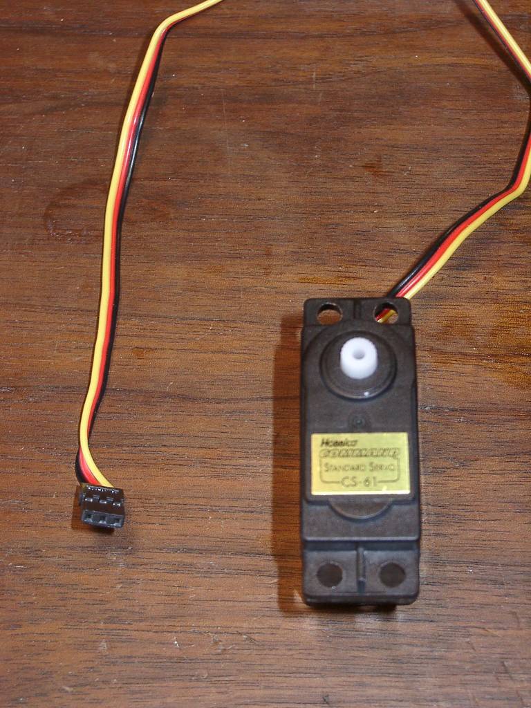
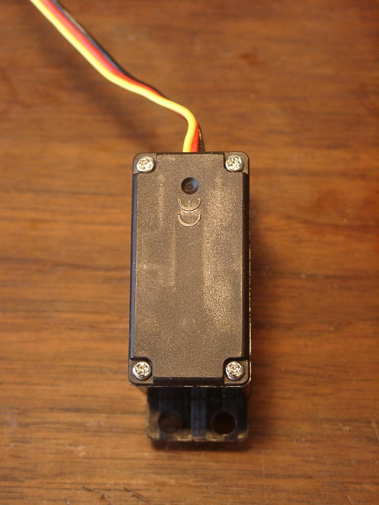
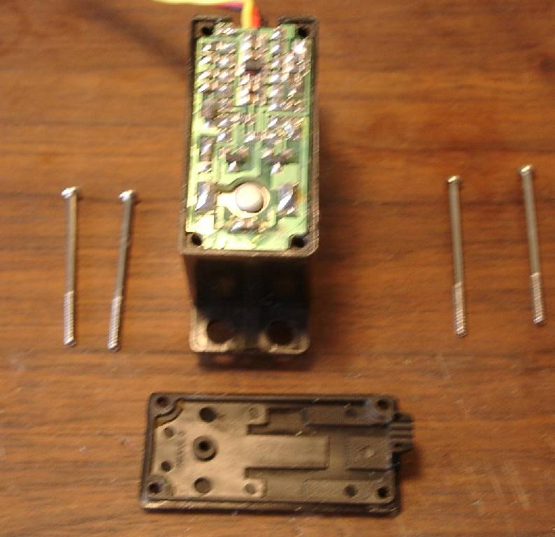
Today's series of pictures are my documentation of Hacking or Modifying a servo for constant rotation. This is a necessary procedure to allow a servo to drive a wheel.
Servos are great motor kits. They have a DC motor, and gears to provide great torque in a package. The circuit built into the package includes an H-Bridge (motor drive interface circuit). Servo's only need 3 wires to interface - and two are power, so only one control line from the controller is needed. The control interface is PWM - or Pulse Width Modulation. This means the length of a pulse tells the control circuitry how to turn the motor. On un-modified servos, the pulse width tells the motor where to turn to in a 180 degree to 320 degree arc (depending on the model of servo). When modified, the circuitry in the servo is tricked into always thinking the shaft is at about 180 degrees (halfway). If you send a pulse width that is jsut a little shorter or a little longer than 1/2 duty (like sending 175 or 185 degrees) the circuitry thinks it only has to adjsut a little bit, and runs the motor slowly one way or another. The further the pulse width is from center, the faster the circuit will try to drive the motor.
Of course the science isn't that exact. It can be tough to send a PWM signal that means stay centered. And any two servos will often have rather different pulse widths for near center. So each servo will require calibration in software to adjust for variances.
The servo you see being hacked in these pictures are from the two inexpesive servos I hacked for what was to become my tuna bot.
I learned later that these were not the best servos to modify for robotics. Some servos are better for long use in robotics - those with bearings. The worst part about these servos that I hacked was the fact that the drive shaft sat on the potentiometer. That meant that when I took out the potentiometers, I no longer had a shaft for the drive to sit on. I hacked a shaft from wood screws, and used bushings that were in the servo kit. Not very elegant, accurate or reliable - but it worked, and it still working fine!
2004-08-08 Update:
Kerwin suggested an improvement for hacking a servo. It seems that some servos now come with the motor glued in. This increased the likelyhood of cracking the circuit board. Kerwin found that it was easier just to unsolder the motor and remove the circuit board that way. Sound like a great idea!