A Blog for Robot News, Opinions and My Pictures that are Robot Related.
Roboton - 1) Abbreviation of Robot Town. 2) Abbreviation of Robot Autonomous.
Friday, July 02, 2004
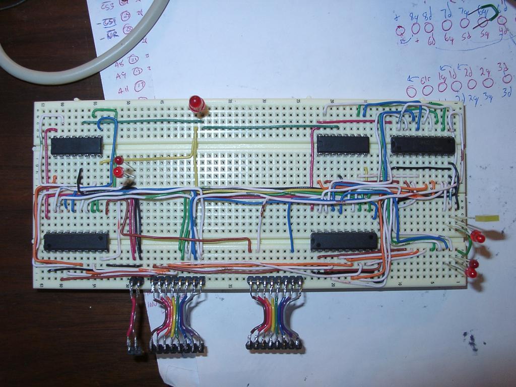
2002-04-13 - Working on HC11 controlled I/O boards, and motor driver boards - this is a prototype motor driver board, with 3 latches and 2 (dual) H-Bridge chips
Picture showing where I bridged resistors on the back side of the I/O board
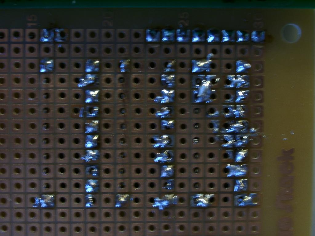
Closeup of the trouble I had soldering the Radio Shack PC board - unlike the other board, it turns out the radio shack terminals needed sanding first to solder well. Thanks to Kerwin for that tip!
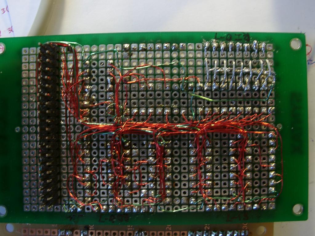
Closer view of the back of the I/O board, featuring the point-to-point wiring
Layout showing final motor control board in progress
back side of I/O board (mostly done) and motor control board (just started)
Closeup of the top of the I/O board. The empty chip is my 6 bit output latch for switch matrix - this chip gave me trouble! I had used a 6 bit chip instead of an 8 bit cip to squeeze it onto the board - but it took me a few tries over quite a number of months to figure out that the latch input was reverse of the 8-bit chip.
Closer view of testing I/O board
View of prototyping motor driving board - yes I can be that anal about laying out wires, but I was going to use this board in an Acroname competition
Testing the IO board with prototyped 2 8-bit latches and H-bridges