A Blog for Robot News, Opinions and My Pictures that are Robot Related.
Roboton - 1) Abbreviation of Robot Town. 2) Abbreviation of Robot Autonomous.
Tuesday, July 20, 2004
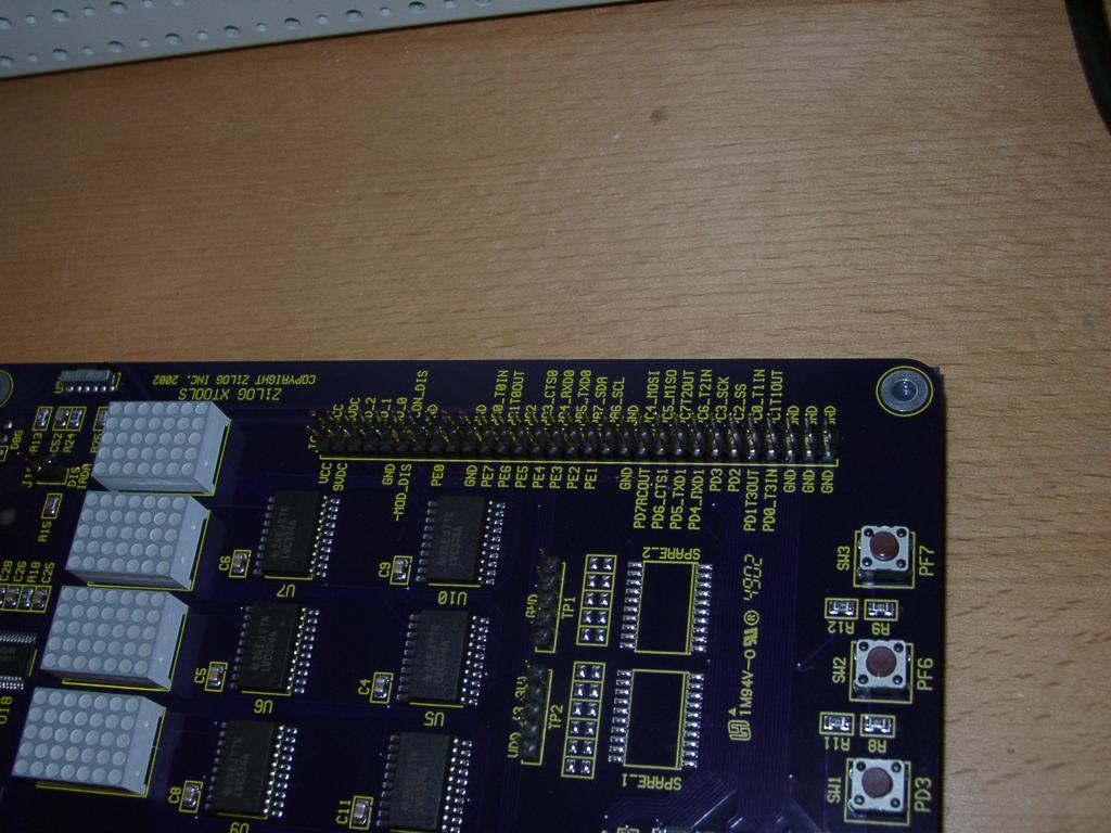
Look at all those connection points!
Closeup of power corner
2003-04-16 - Z8 Encore package
Monday, July 19, 2004
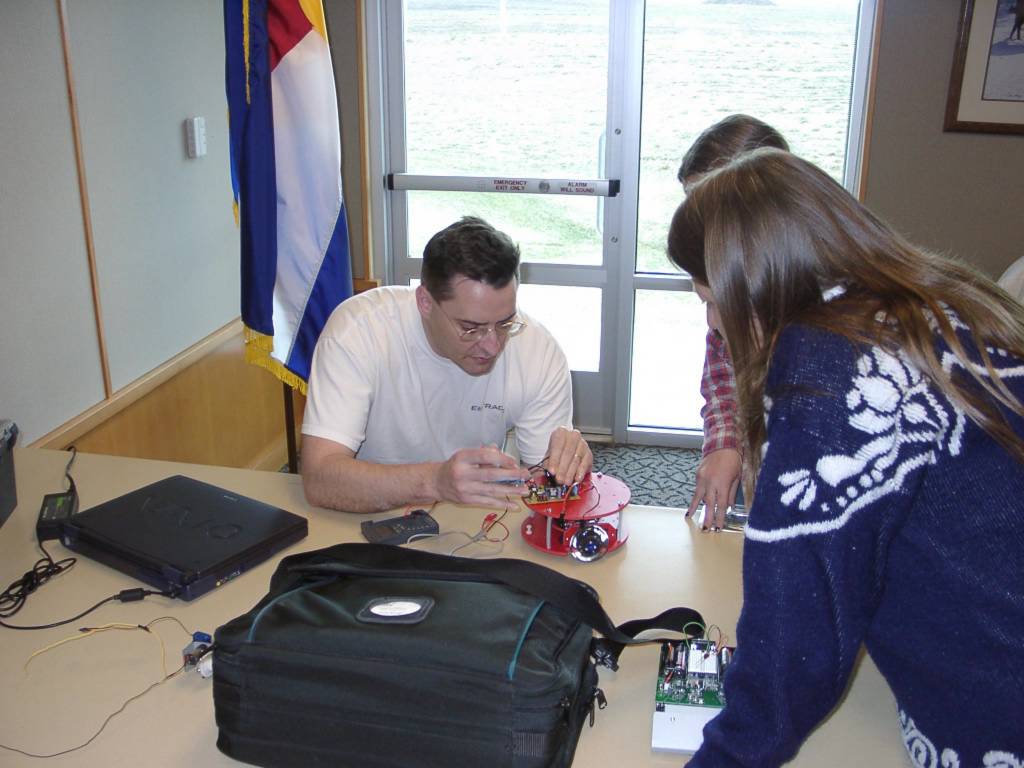
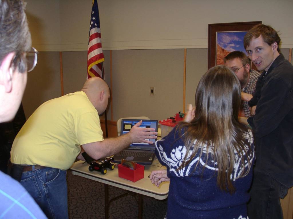
2003-04-05 - DARC - Kerwin showing how the red platform robot works
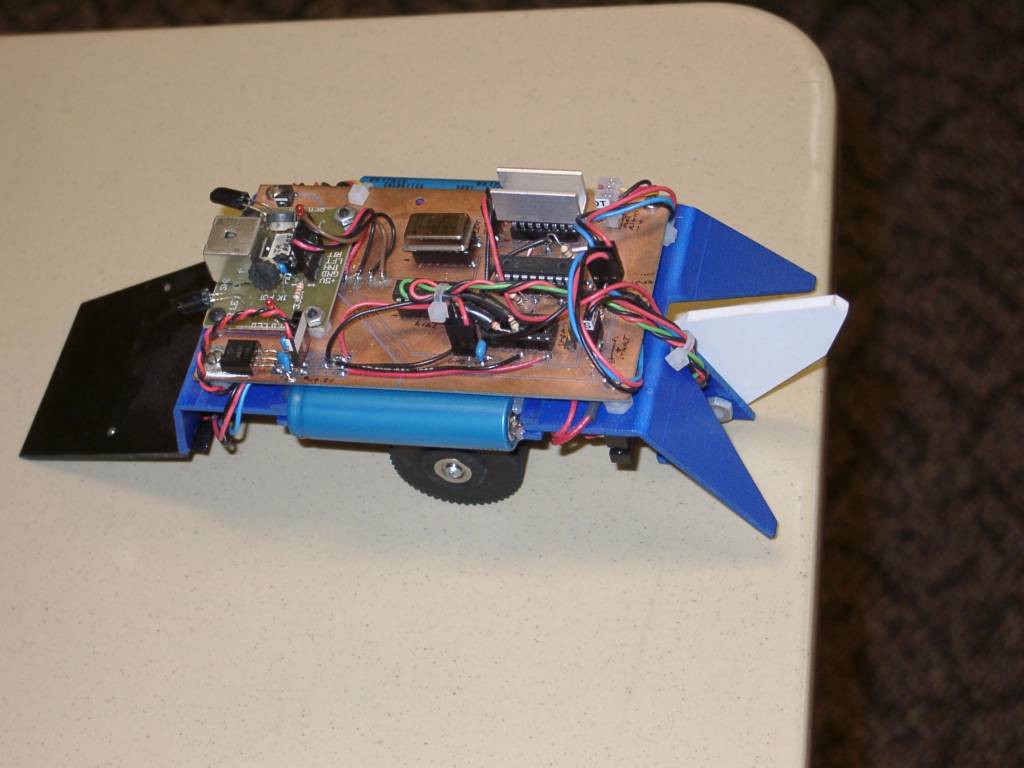
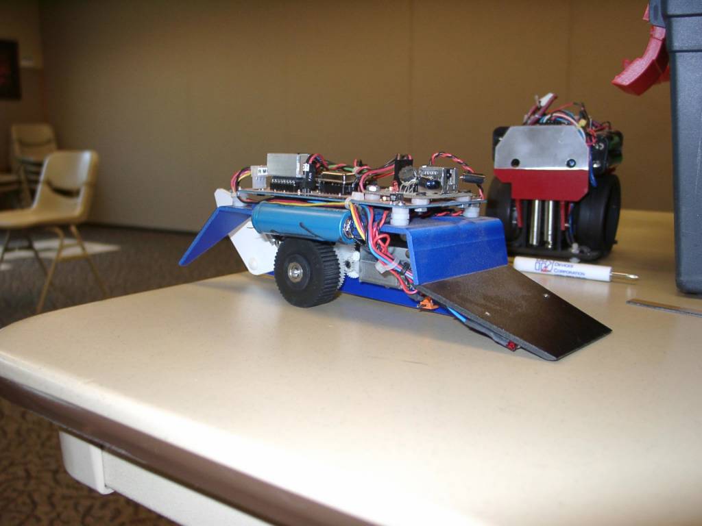
An Atmel TTT bot on a nice red platform
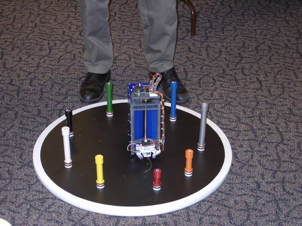
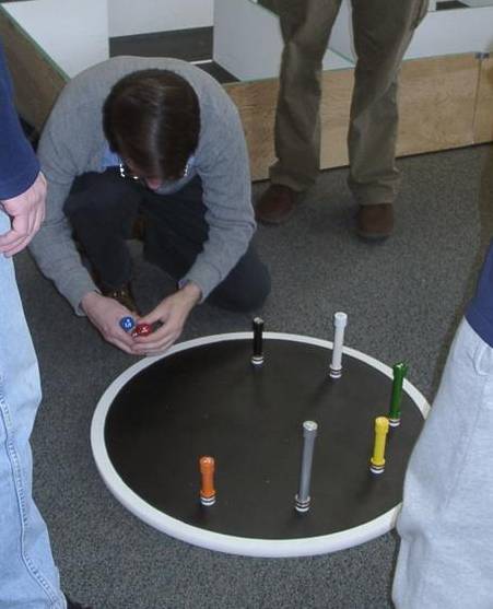
Ed starting his object finder
Ed's object finder on the challange
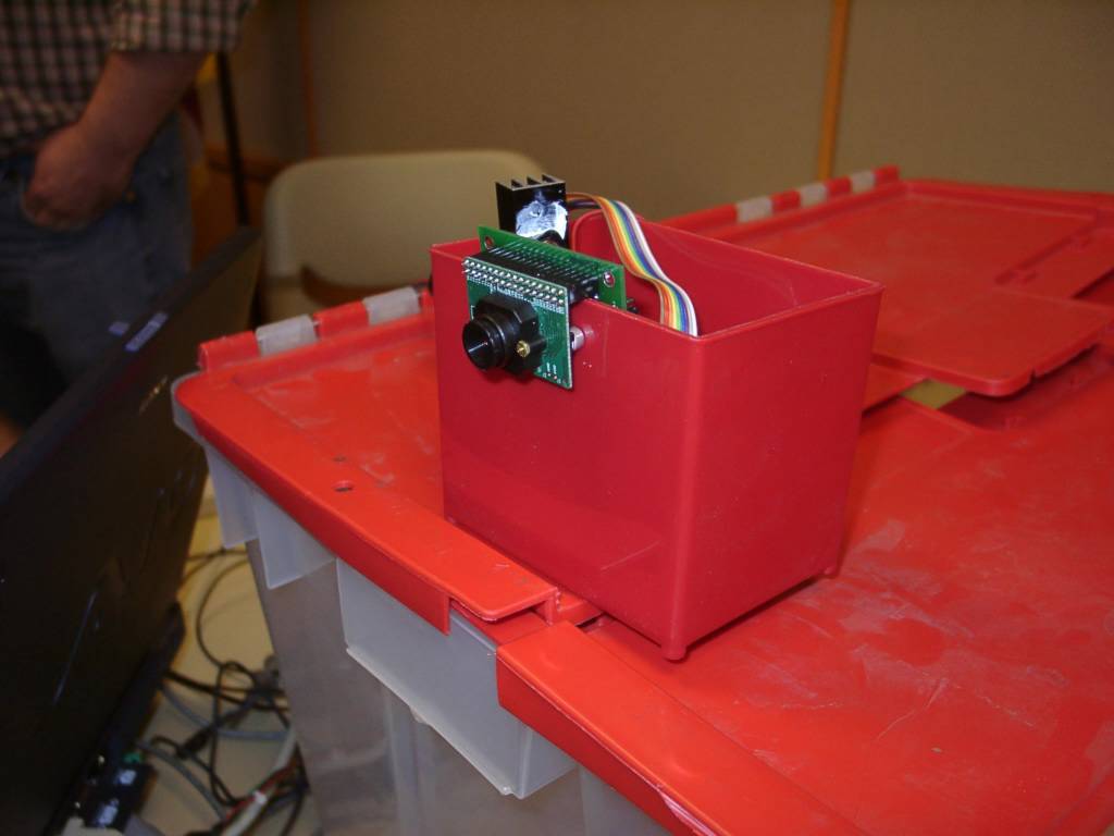
Showing a CMU cam in action
Front of a CMU cam
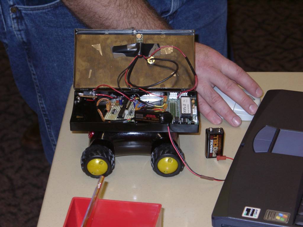
An OOpic driven robot with it's cover open
Closeup of the back of a CMU cam board
Demo of a CMU cam
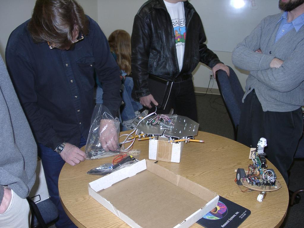
Robots on the table
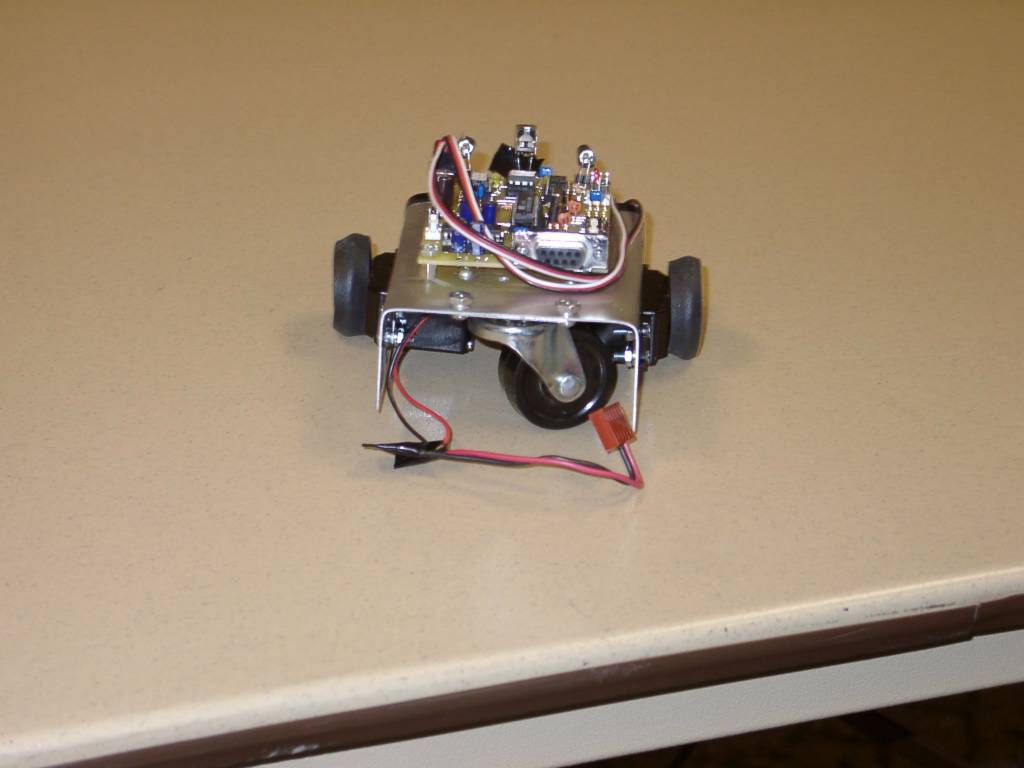
A robot with a caster
Another view of the sumo robot that starts out standing vertically
A couple of Sumo bots - the foreground robot starts out standing upright, and drops to it's wheels
Closeup of Ed's object finder
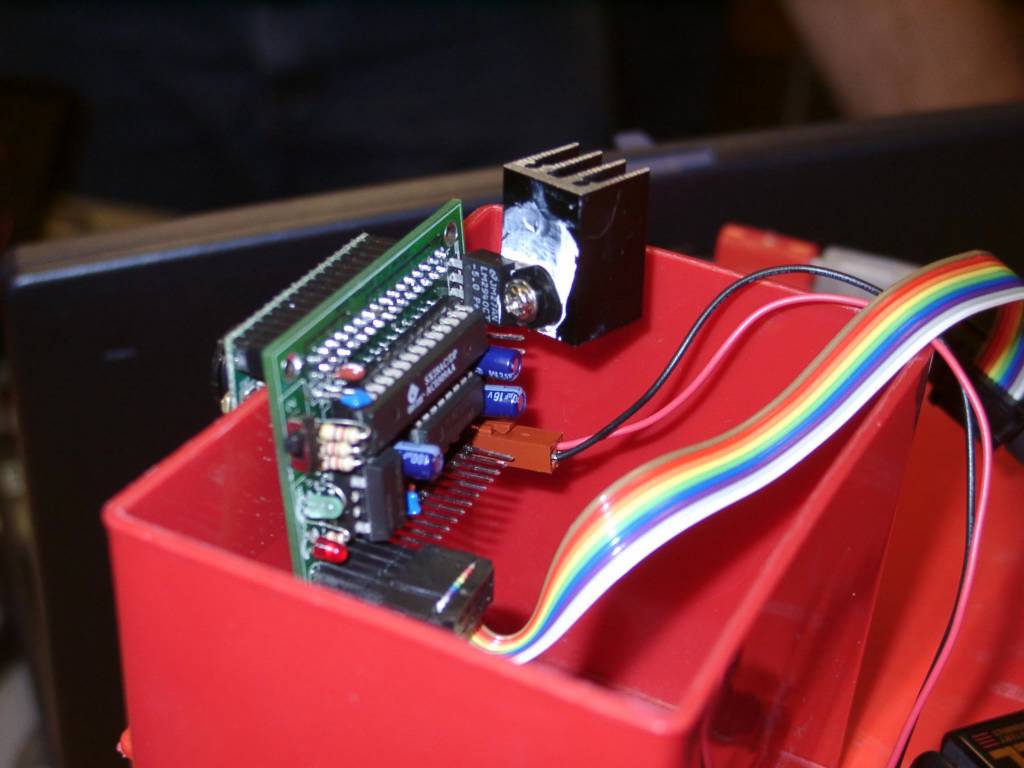
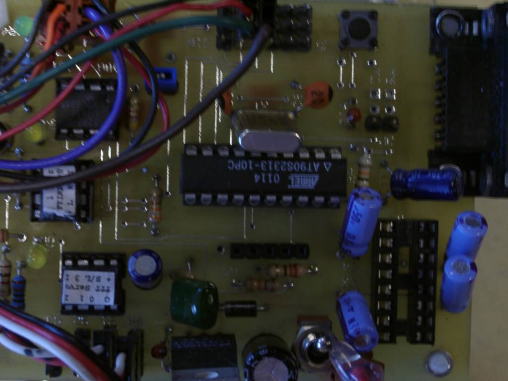
Closeup of an Atmel 90S2313 on a TTT board
Closeup of another's TTT Atmel board
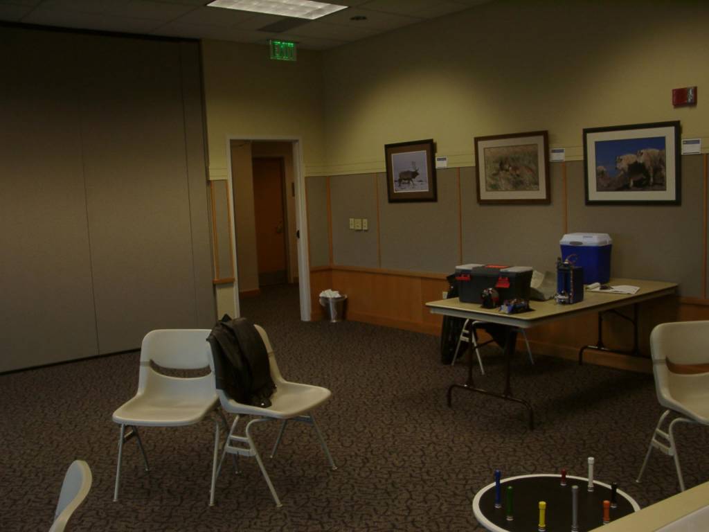
2003-04-05 DARC - No people - Object finder challenge in lower right
Saturday, July 17, 2004
2003-03-24 - Workbench - building and testing my custom I/O and motor driver boards with my HC11 controller board
Top of my custom I/O and motor driver board - this board combo provides 6x8 switch matrix and can drive 10 motors - with room and logic on the motor driver board to contol 2 more motors
Back of my custom I/O board and motor driver boards, hooked up
Back of my home-brew I/O baord, buffered input on lower left, data bus from the controller board on the right
Back of my home brew motor driver board
Closeup of the back of the 5 8-bit latches on the motor driver board
Closeup of the back of the H-bridge section of my home-brew motor driver board
Closeup of the back of the motor driver board - H-Bridge circuits on the left, 8-bit latch chips on the right
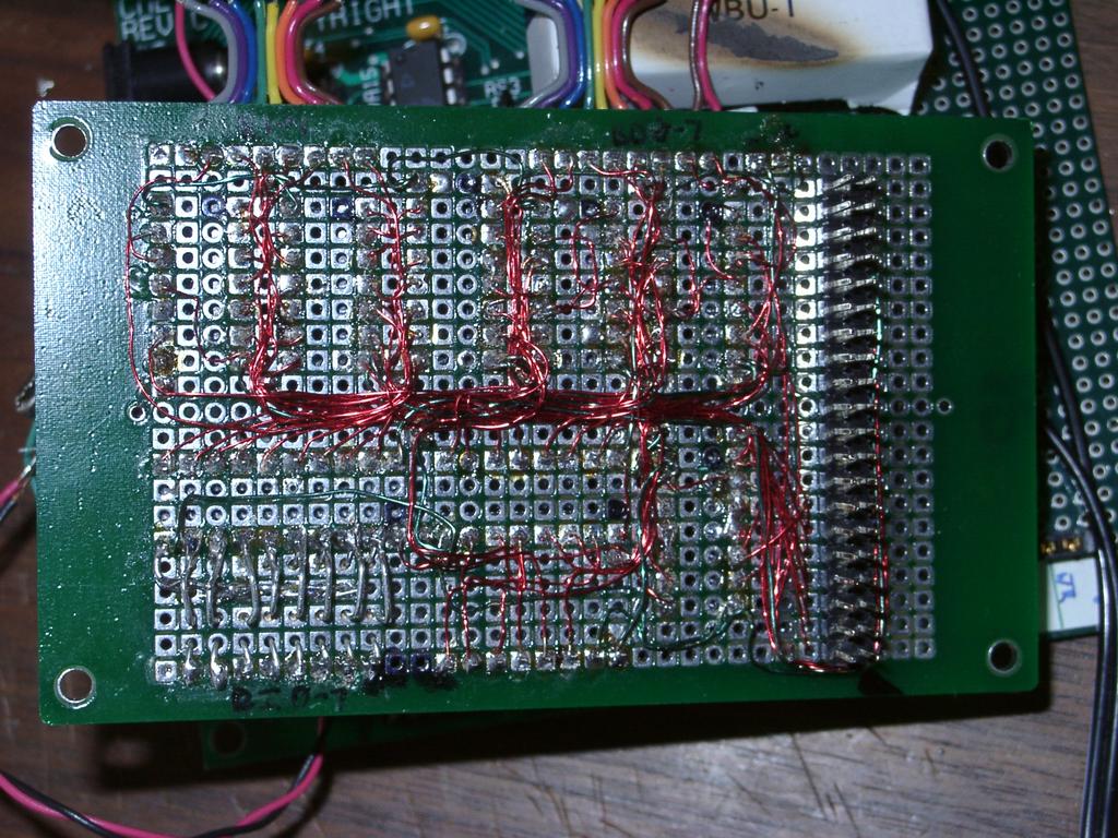
Closeup of the back of the 6x8 switch matrix I/O ports
2003-03-24 - Closeup of the 6 bit output, 8 bit buffered input custom board
Friday, July 16, 2004
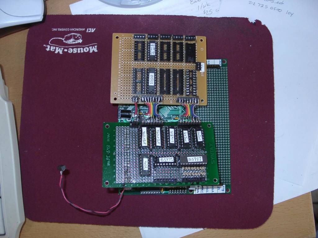
2003-03-17 - The I/O board and motor driver board sitting on top of the HC11 board
Top of I/O board with all the chips installed - all the chips are labeled with stickers - the 2 horizonal chips are L 6-bit latch out, R 8-bit buffer input, for use in an 8x6 switch input matrix
The top of the motor driver board - only one 8-bit latch and one H-Bridge chip installed - seperate power for the motors is the plug in the middle on the right
The backs of both the I/O board and the motor driver board
I/O board back - you can see the ribbon cables at the top that go to the motor driver board
Overview of whole motor driver board - H-Bridges at the top, 8-bit latches at the bottom - you can see there is room for one mroe set of chips on the right if I wanted
Back of motor driver board, back of 3 H-Bridge chips - output to motors is at the top in this picture
Closeup of the motor driving wiring - this is the back side of a dual H-Bridge chip
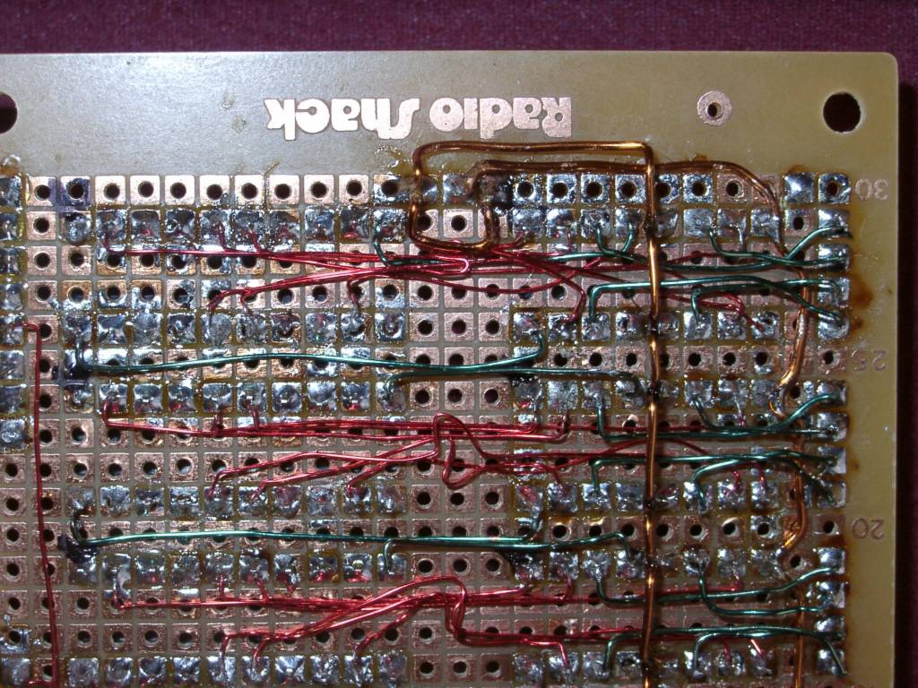
Closeup of motor driver board - red wires are logic, green wires are power to the chips and output to the motors - the copper colored wire is the motor source
2003-03-17 - My homebrew HC11 I/O + Motor driver board - Closeup of wires on the motor driver board
Thursday, July 15, 2004
2003-02-15 Joint DARC and FRR robot clubs at Acroname - 3 wheel, multi-direction robots playing follow the leader, CMU Cam watching the orange ball
Ed setting up the object finder challenge
The two groups chatting about robots
Inside the furry robot
Demonstrating The Stampy Class Fire Fighting Robots