2002-04-18 - School science display of Lego Mindstorms - showing the robot, Acroname's Robo02, and describing the robot and competition
Mindstorms Robot on our own homemade test course, picture for school science display
2002-04-16 - Lego Mindstorms robot as built by my eldest son (with a little help) for competition at Acroname's Robo02 - Picture for use on a display board for school science project display
Monday, July 05, 2004
2002-04-06 - Robot platform I was building for Robo02
Top of the platform - sitting on the closed laptop used for programming the HC11
Bottom of the platform - showing the batteries installed underneath and upsidedown
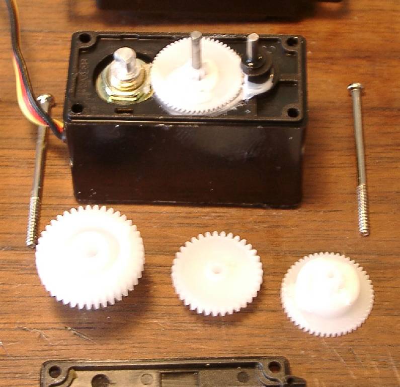
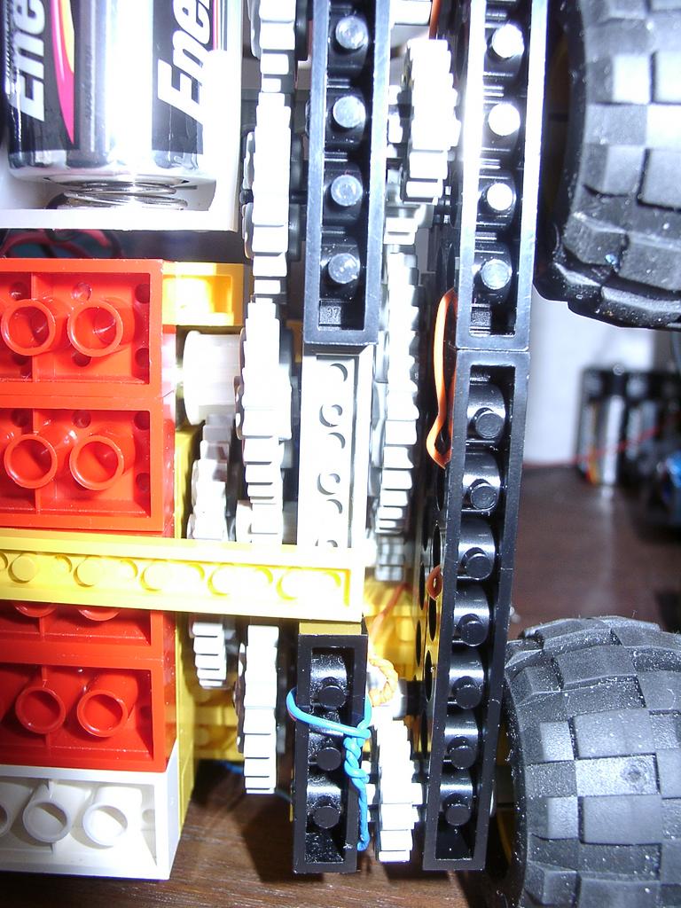
Closeup of gear train
Closeup of optical sensors - small red LEDs on the corner, CDs cells in the center (CDs cell=optical resistor) - The CDs cells are hooked to A/D channels
Front end of Lego platform - notice 3 square bricks in the middle - those are optical sensor housing
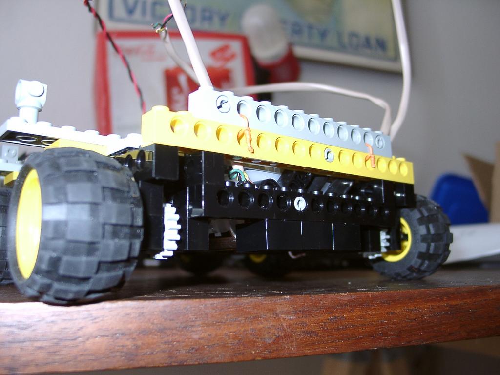
2002-04-06 - Lego platform I was working on for Acroname's Robo02 - was driven by HC11+I/O+motor driver board
Holding the Lego together with twisted phone wire
Rear of Lego platform - drive wire for rear motor
Sunday, July 04, 2004
2002-04-05 Acroname's Robo02 - Student line following
Student line cometitors
A walking bot on the line course
2002-04-05 - Acroname's Robo02 - View on big video screen of line following course
Saturday, July 03, 2004
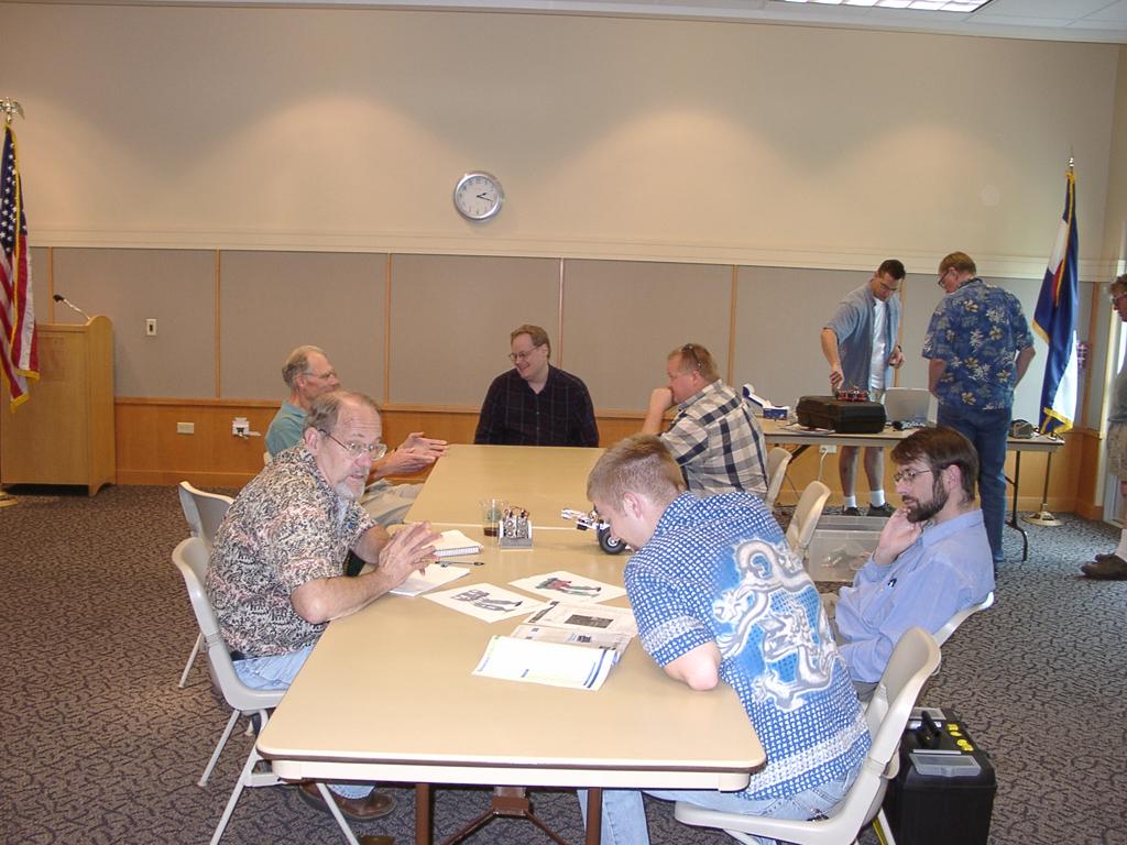
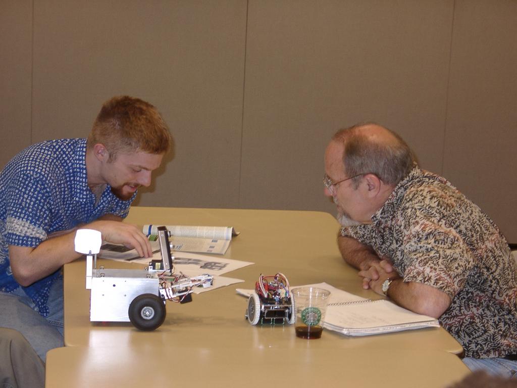
2004-07-03 - DARC Robot Meeting - A great turnout for July 3rd!