A Blog for Robot News, Opinions and My Pictures that are Robot Related.
Roboton - 1) Abbreviation of Robot Town. 2) Abbreviation of Robot Autonomous.
Friday, July 16, 2004
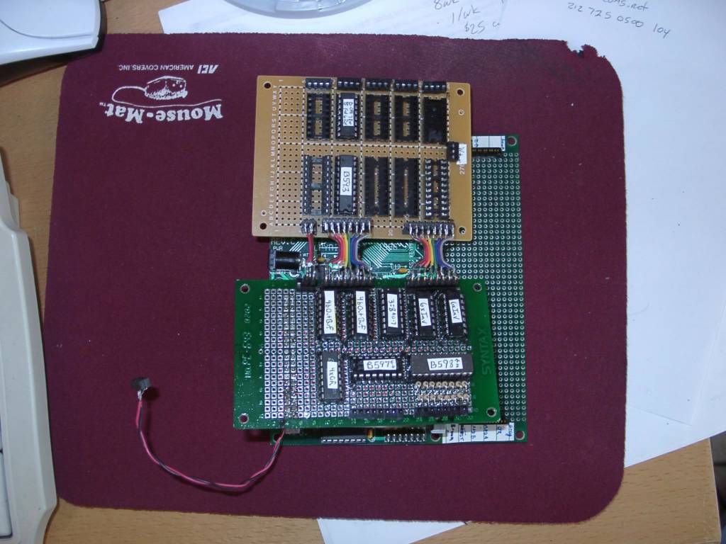
2003-03-17 - The I/O board and motor driver board sitting on top of the HC11 board
Top of I/O board with all the chips installed - all the chips are labeled with stickers - the 2 horizonal chips are L 6-bit latch out, R 8-bit buffer input, for use in an 8x6 switch input matrix
The top of the motor driver board - only one 8-bit latch and one H-Bridge chip installed - seperate power for the motors is the plug in the middle on the right
The backs of both the I/O board and the motor driver board
I/O board back - you can see the ribbon cables at the top that go to the motor driver board
Overview of whole motor driver board - H-Bridges at the top, 8-bit latches at the bottom - you can see there is room for one mroe set of chips on the right if I wanted
Back of motor driver board, back of 3 H-Bridge chips - output to motors is at the top in this picture
Closeup of the motor driving wiring - this is the back side of a dual H-Bridge chip
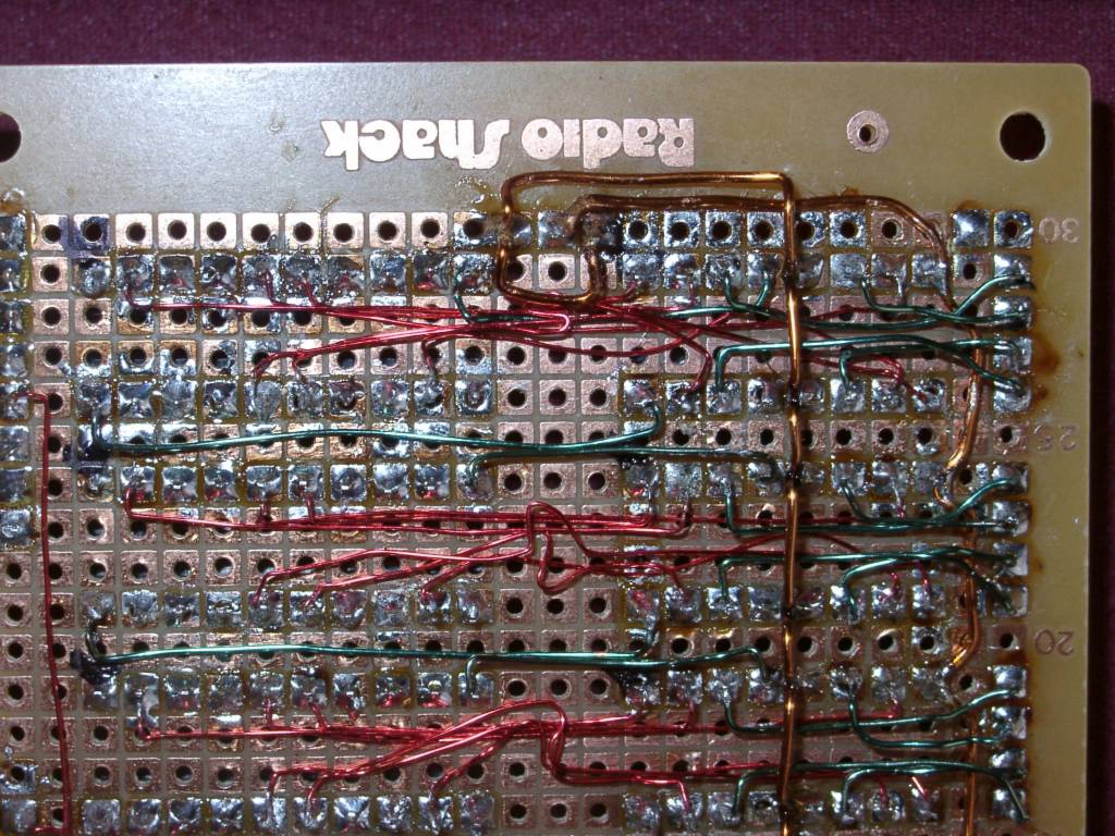
Closeup of motor driver board - red wires are logic, green wires are power to the chips and output to the motors - the copper colored wire is the motor source
2003-03-17 - My homebrew HC11 I/O + Motor driver board - Closeup of wires on the motor driver board