A Blog for Robot News, Opinions and My Pictures that are Robot Related.
Roboton - 1) Abbreviation of Robot Town. 2) Abbreviation of Robot Autonomous.
Wednesday, July 21, 2004
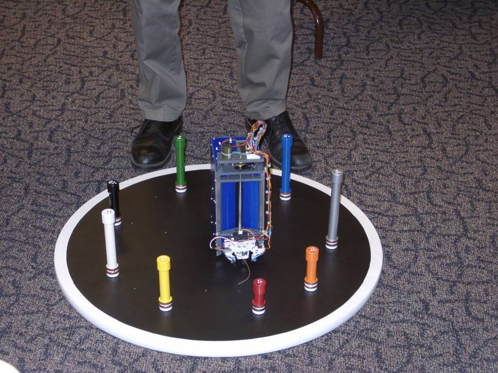
Acroname obstacle challenge course
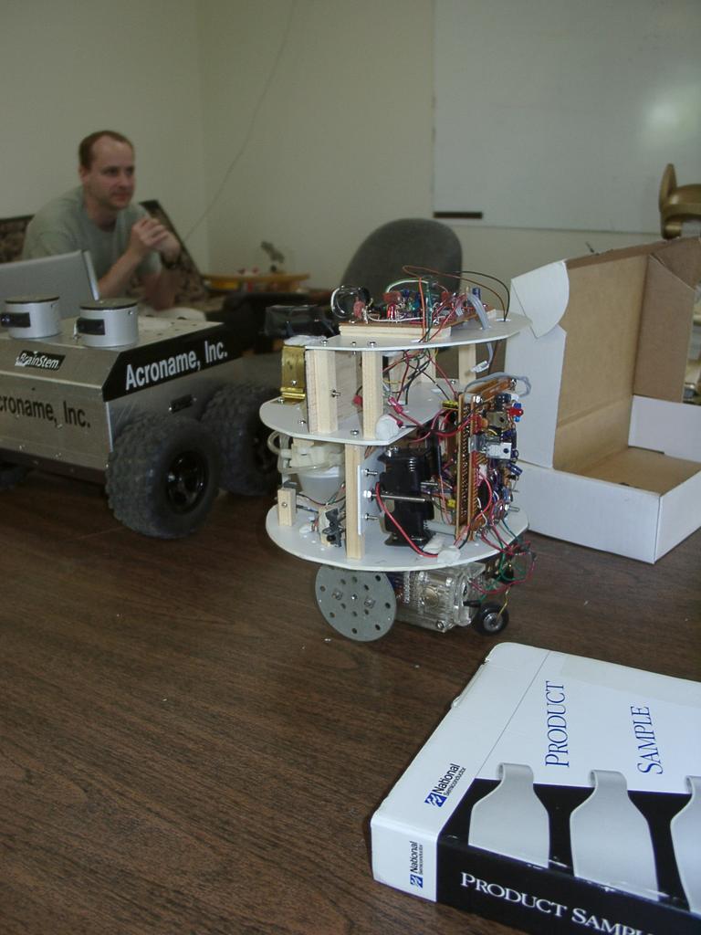
Multi-level platform robot
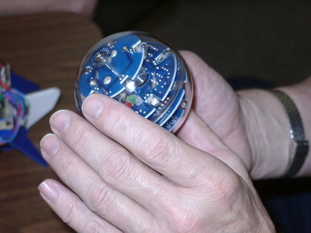
LED challenge ball, closeup
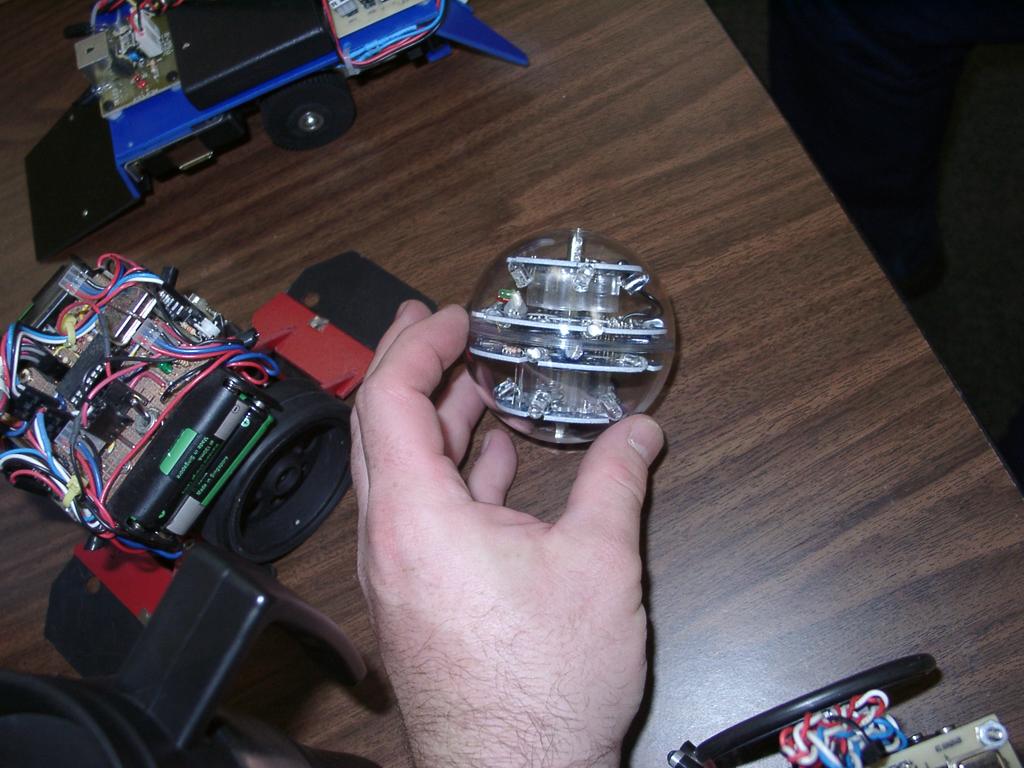
LED challenge ball
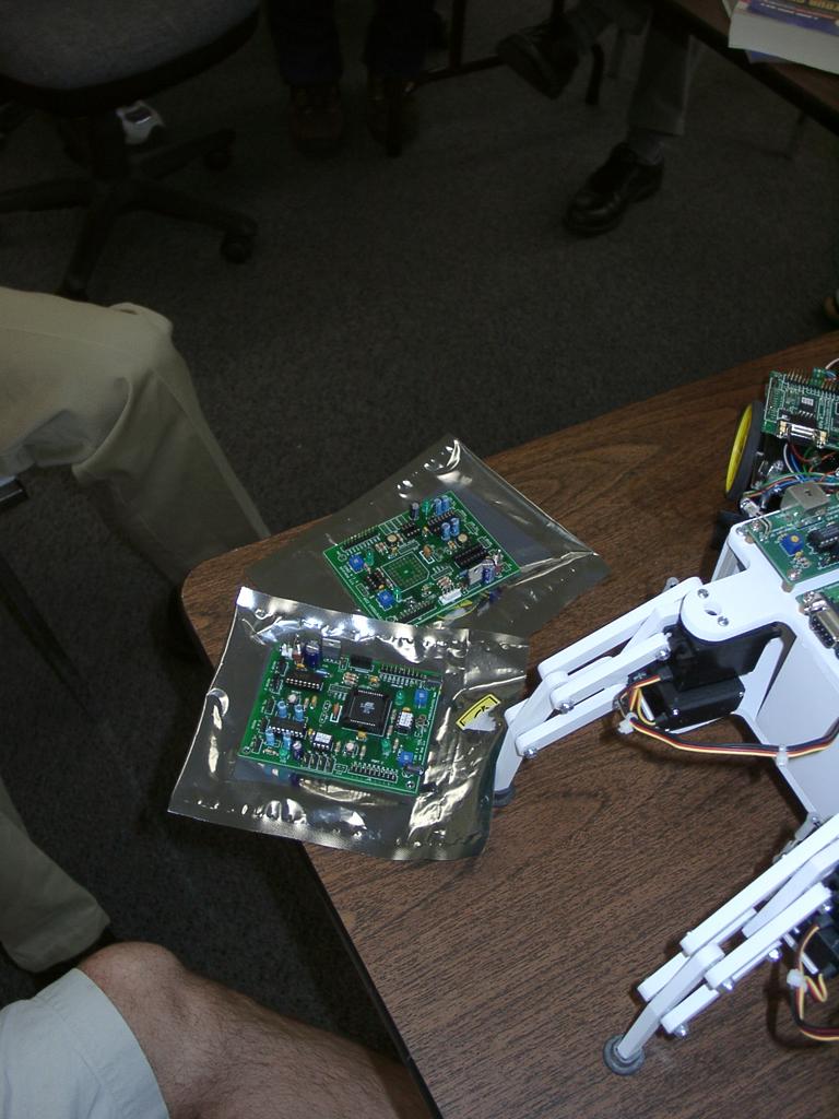
New versions of the TTT boards
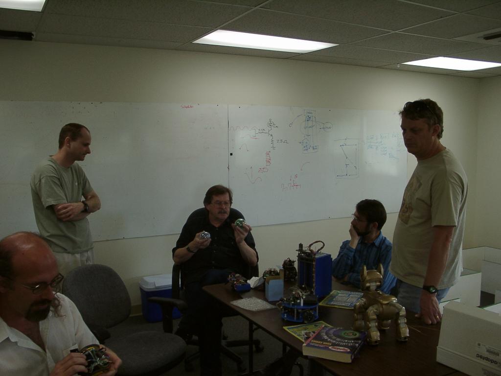
2003-05-17 - Joint meeting of DARC and FRR at Acroname
Tuesday, July 20, 2004
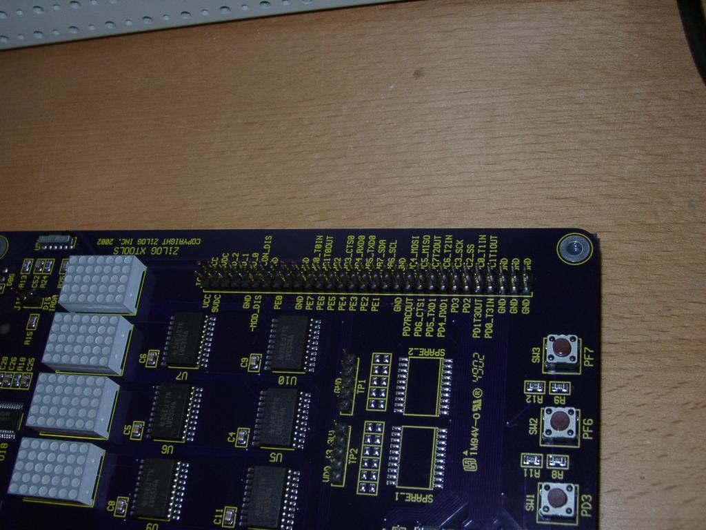
The whole board, plugged in
Testing the LED dot-matrix displays
The MCU (CPU Microcontroller)
The serial (RS232) connector interface
Look at all those connection points!
Closeup of power corner
2003-04-16 - Z8 Encore package
Monday, July 19, 2004
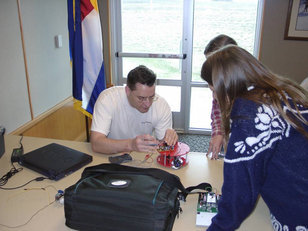
2003-04-05 - DARC - Kerwin showing how the red platform robot works
An Atmel TTT bot on a nice red platform
Ed starting his object finder
Ed's object finder on the challange
Showing a CMU cam in action
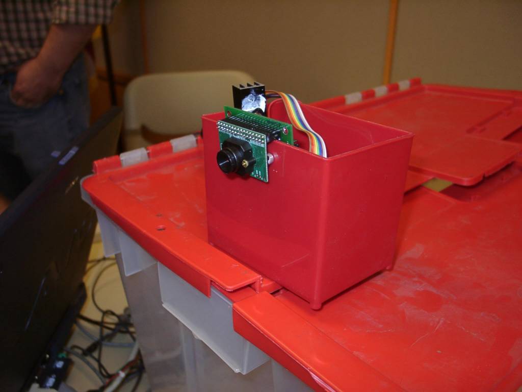
Front of a CMU cam
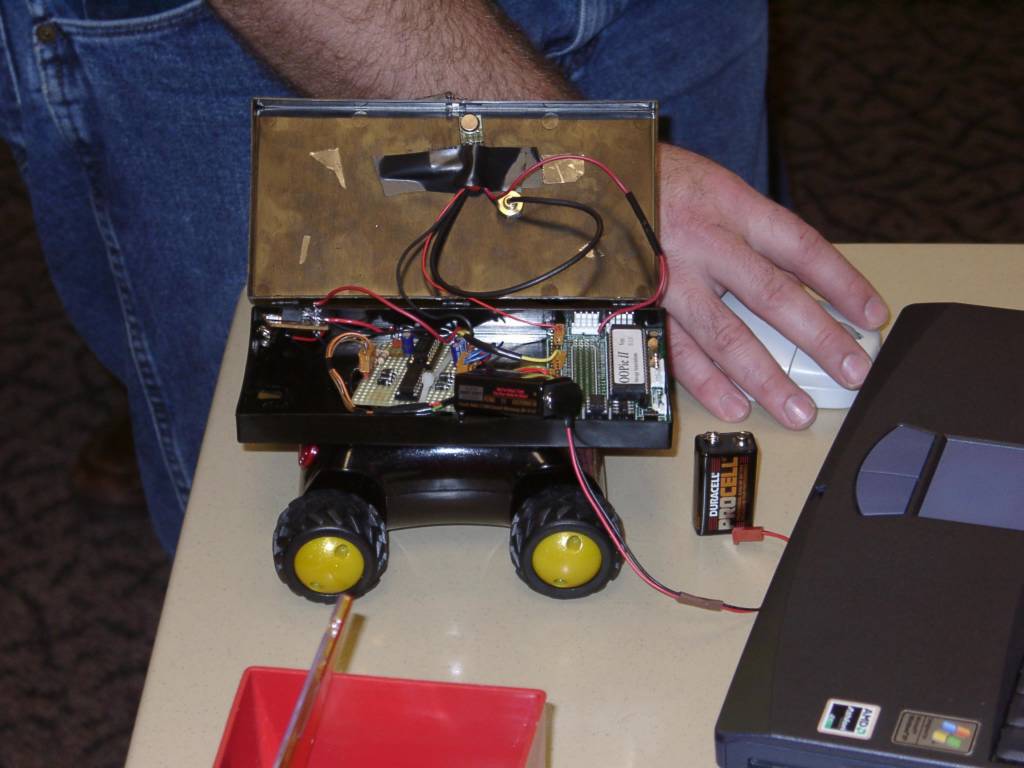
An OOpic driven robot with it's cover open
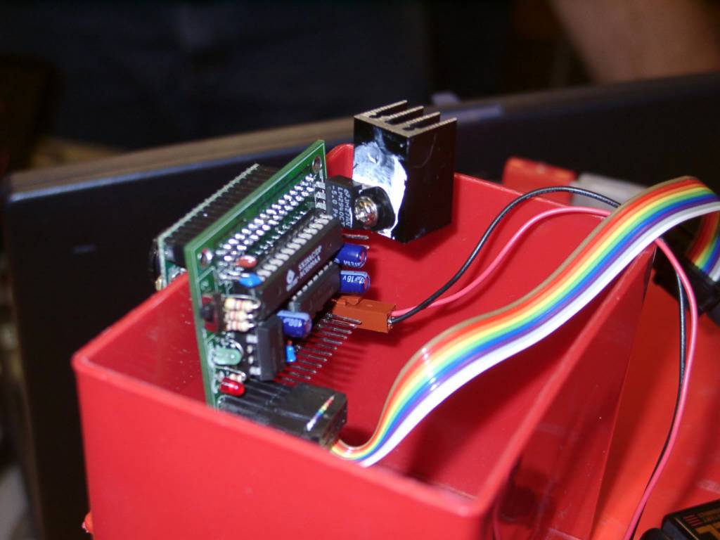
Closeup of the back of a CMU cam board
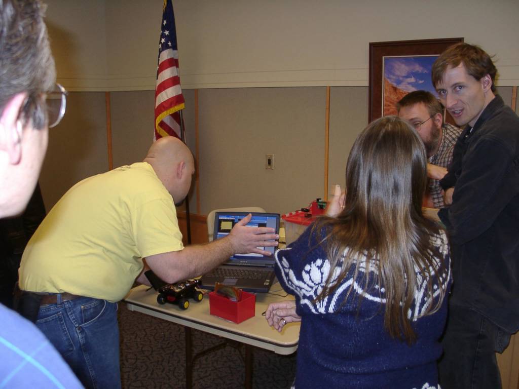
Demo of a CMU cam
Robots on the table
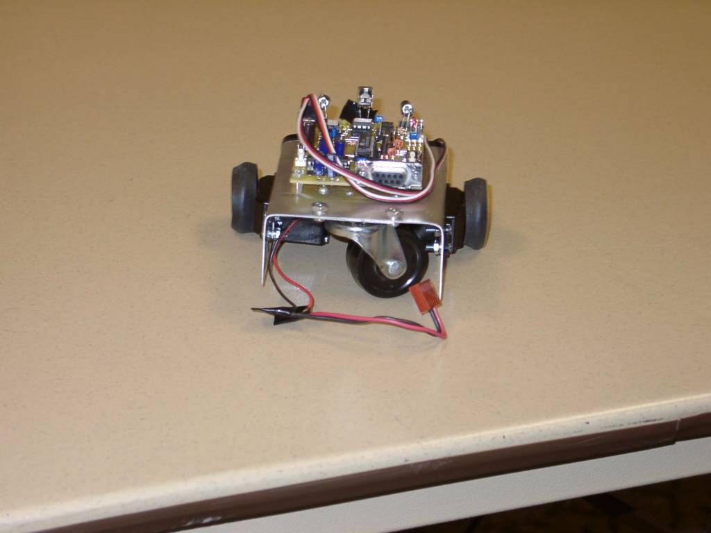
A robot with a caster
Another view of the sumo robot that starts out standing vertically
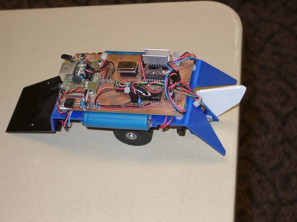
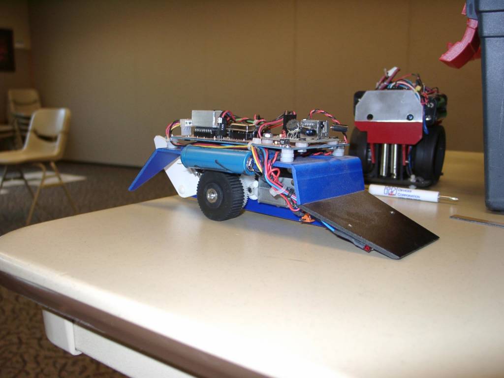
A couple of Sumo bots - the foreground robot starts out standing upright, and drops to it's wheels
Closeup of Ed's object finder
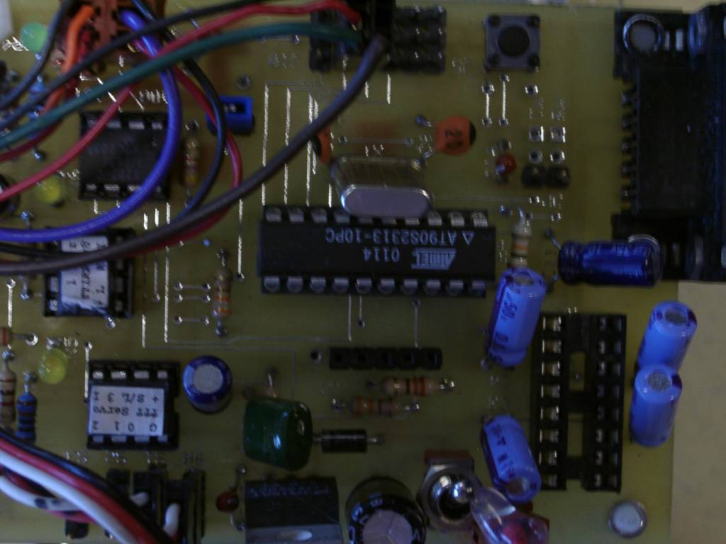
Closeup of an Atmel 90S2313 on a TTT board
Closeup of another's TTT Atmel board
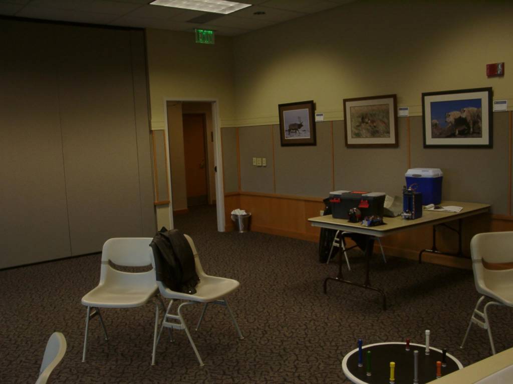
2003-04-05 DARC - No people - Object finder challenge in lower right
Saturday, July 17, 2004
2003-03-24 - Workbench - building and testing my custom I/O and motor driver boards with my HC11 controller board
Top of my custom I/O and motor driver board - this board combo provides 6x8 switch matrix and can drive 10 motors - with room and logic on the motor driver board to contol 2 more motors
Back of my custom I/O board and motor driver boards, hooked up
Back of my home-brew I/O baord, buffered input on lower left, data bus from the controller board on the right
Back of my home brew motor driver board
Closeup of the back of the 5 8-bit latches on the motor driver board
Closeup of the back of the H-bridge section of my home-brew motor driver board
Closeup of the back of the motor driver board - H-Bridge circuits on the left, 8-bit latch chips on the right
Closeup of the back of the 6x8 switch matrix I/O ports
2003-03-24 - Closeup of the 6 bit output, 8 bit buffered input custom board
Friday, July 16, 2004
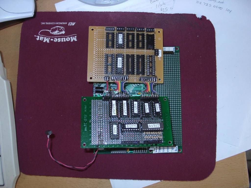
2003-03-17 - The I/O board and motor driver board sitting on top of the HC11 board
Top of I/O board with all the chips installed - all the chips are labeled with stickers - the 2 horizonal chips are L 6-bit latch out, R 8-bit buffer input, for use in an 8x6 switch input matrix
The top of the motor driver board - only one 8-bit latch and one H-Bridge chip installed - seperate power for the motors is the plug in the middle on the right
The backs of both the I/O board and the motor driver board
I/O board back - you can see the ribbon cables at the top that go to the motor driver board
Overview of whole motor driver board - H-Bridges at the top, 8-bit latches at the bottom - you can see there is room for one mroe set of chips on the right if I wanted
Back of motor driver board, back of 3 H-Bridge chips - output to motors is at the top in this picture
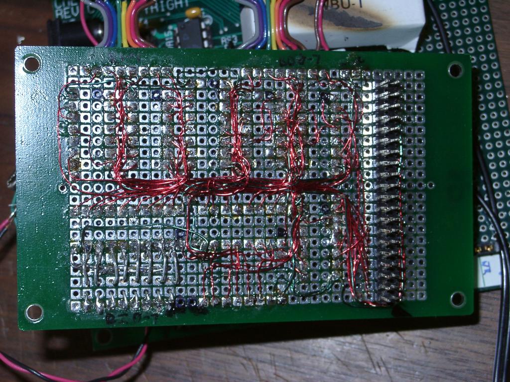
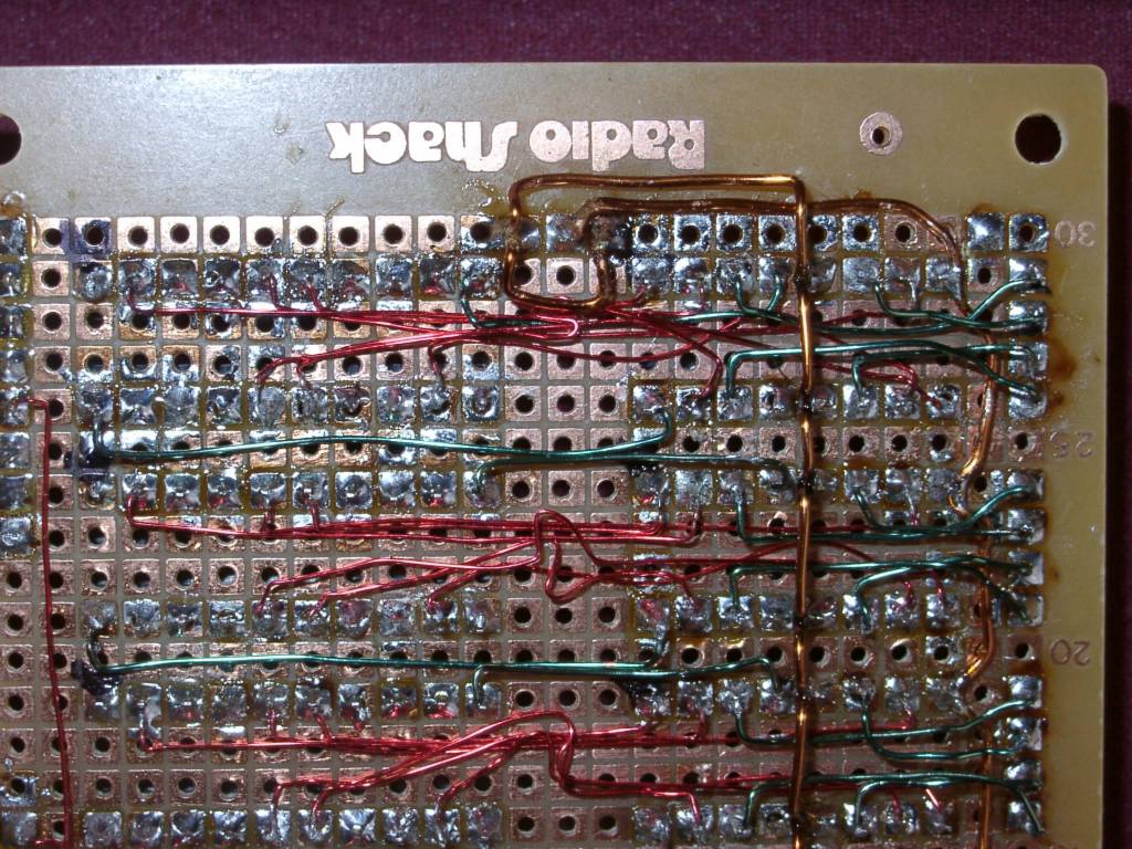
Closeup of the motor driving wiring - this is the back side of a dual H-Bridge chip
Closeup of motor driver board - red wires are logic, green wires are power to the chips and output to the motors - the copper colored wire is the motor source
2003-03-17 - My homebrew HC11 I/O + Motor driver board - Closeup of wires on the motor driver board