A Blog for Robot News, Opinions and My Pictures that are Robot Related.
Roboton - 1) Abbreviation of Robot Town. 2) Abbreviation of Robot Autonomous.
Monday, July 05, 2004
2002-04-06 - Robot platform I was building for Robo02
Top of the platform - sitting on the closed laptop used for programming the HC11
Bottom of the platform - showing the batteries installed underneath and upsidedown
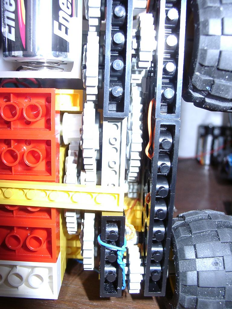
Closeup of gear train
Closeup of optical sensors - small red LEDs on the corner, CDs cells in the center (CDs cell=optical resistor) - The CDs cells are hooked to A/D channels
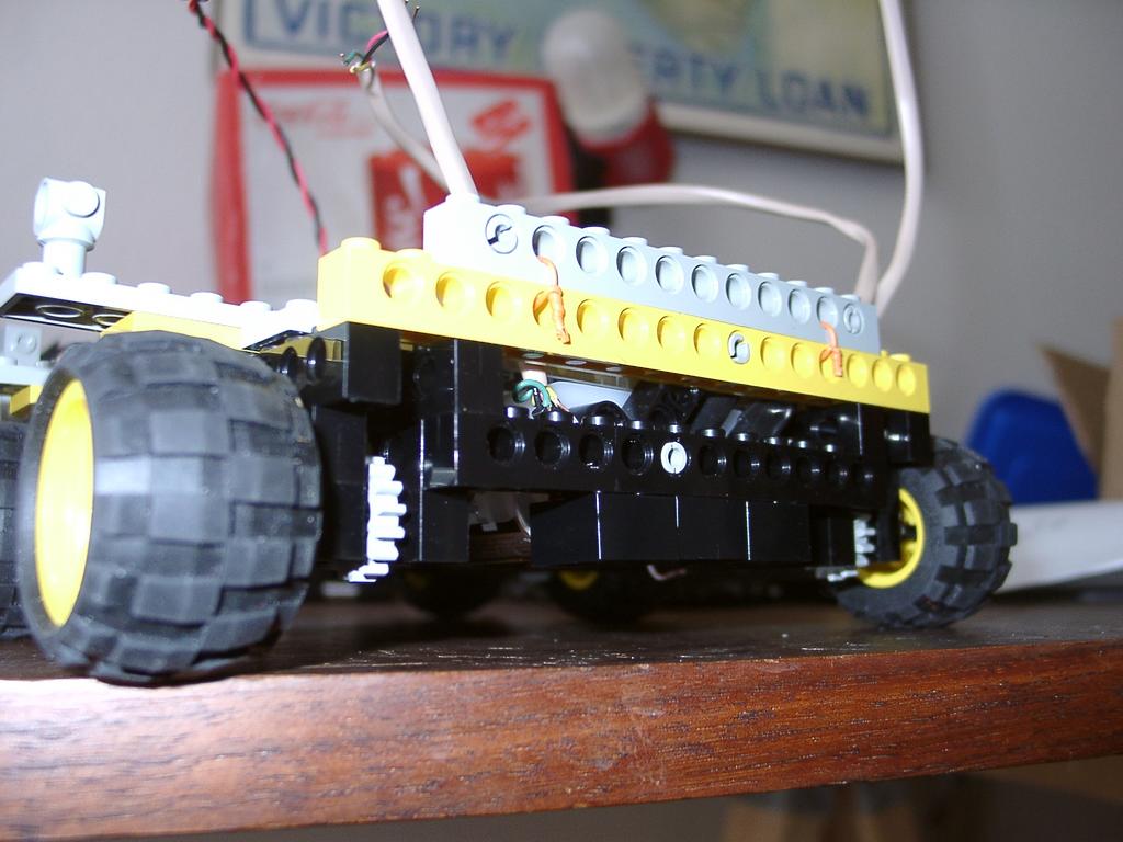
Front end of Lego platform - notice 3 square bricks in the middle - those are optical sensor housing
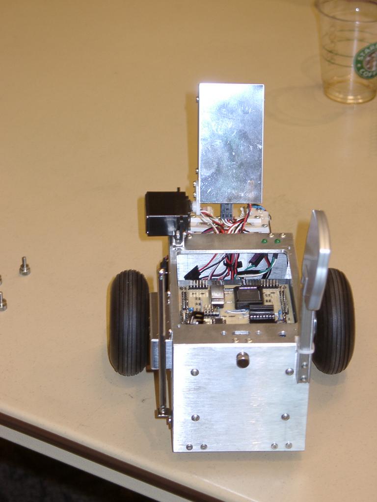
2002-04-06 - Lego platform I was working on for Acroname's Robo02 - was driven by HC11+I/O+motor driver board
Holding the Lego together with twisted phone wire
Rear of Lego platform - drive wire for rear motor
Sunday, July 04, 2004
2002-04-05 Acroname's Robo02 - Student line following
Student line cometitors
A walking bot on the line course
2002-04-05 - Acroname's Robo02 - View on big video screen of line following course
Saturday, July 03, 2004
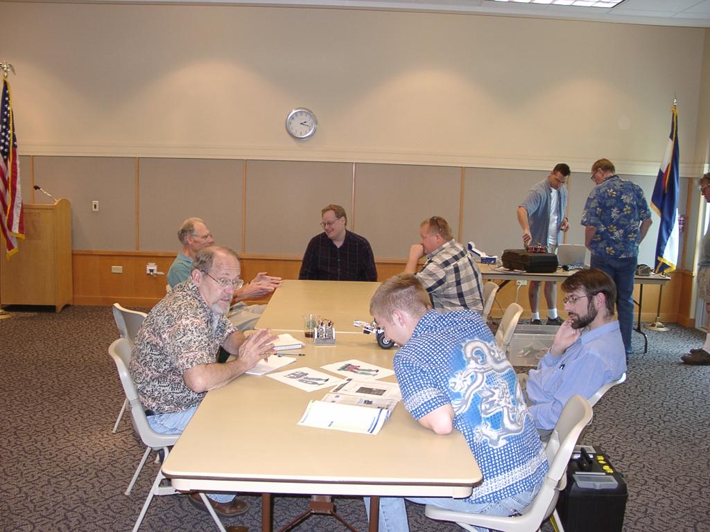
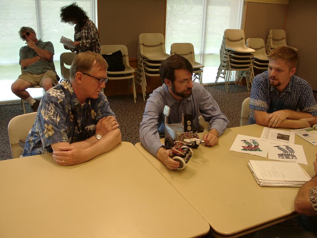
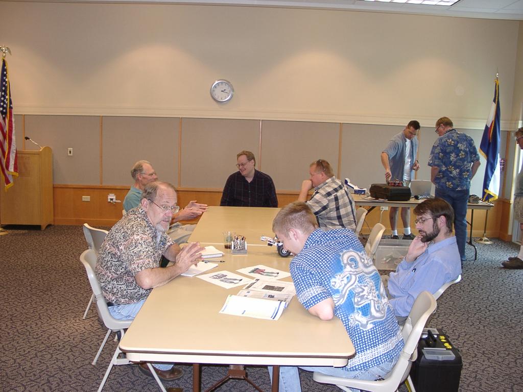
2004-07-03 - DARC Robot Meeting - A great turnout for July 3rd!
A meeting of minds
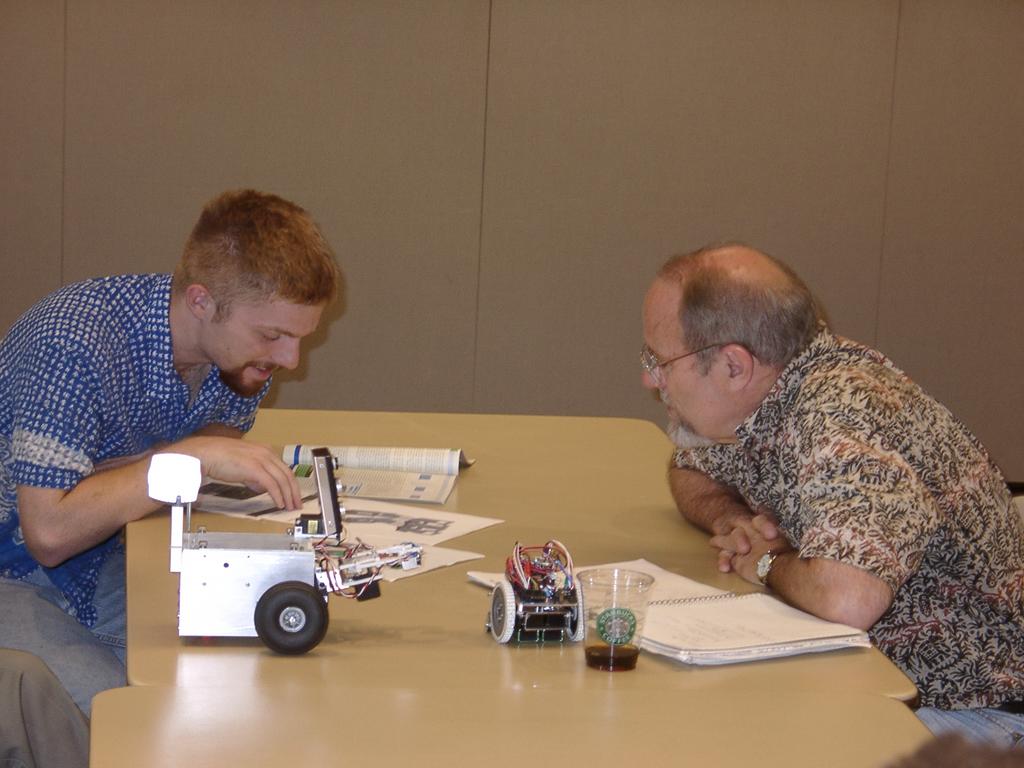
Compairing notes
Ed describing his homebrew sonar
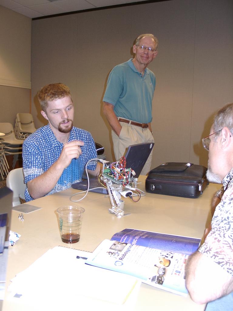
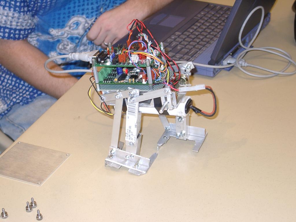
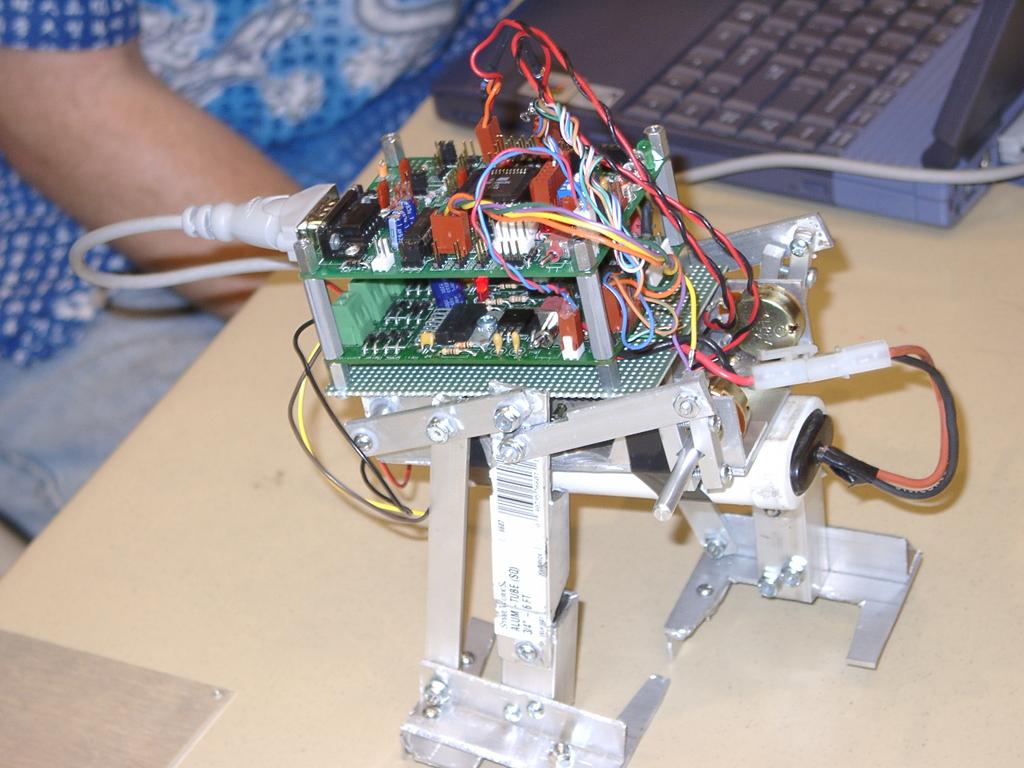
A biped walker
2004-07-03 - DARC - Robot meeting: A great turnout for July
Describing the walker
Walker in action
Walker, getting some help
Kerwin describing
Ed talking about his Marsrover
Darcboard on a Platform
Walker in action
Ed's latest Sumo - Second place winner!
Kerwin adjusting
Ed's Marsrover v2 opened up
2004-07-03 Darcboard and Wires
Friday, July 02, 2004
2002-04-13 - Working on HC11 controlled I/O boards, and motor driver boards - this is a prototype motor driver board, with 3 latches and 2 (dual) H-Bridge chips
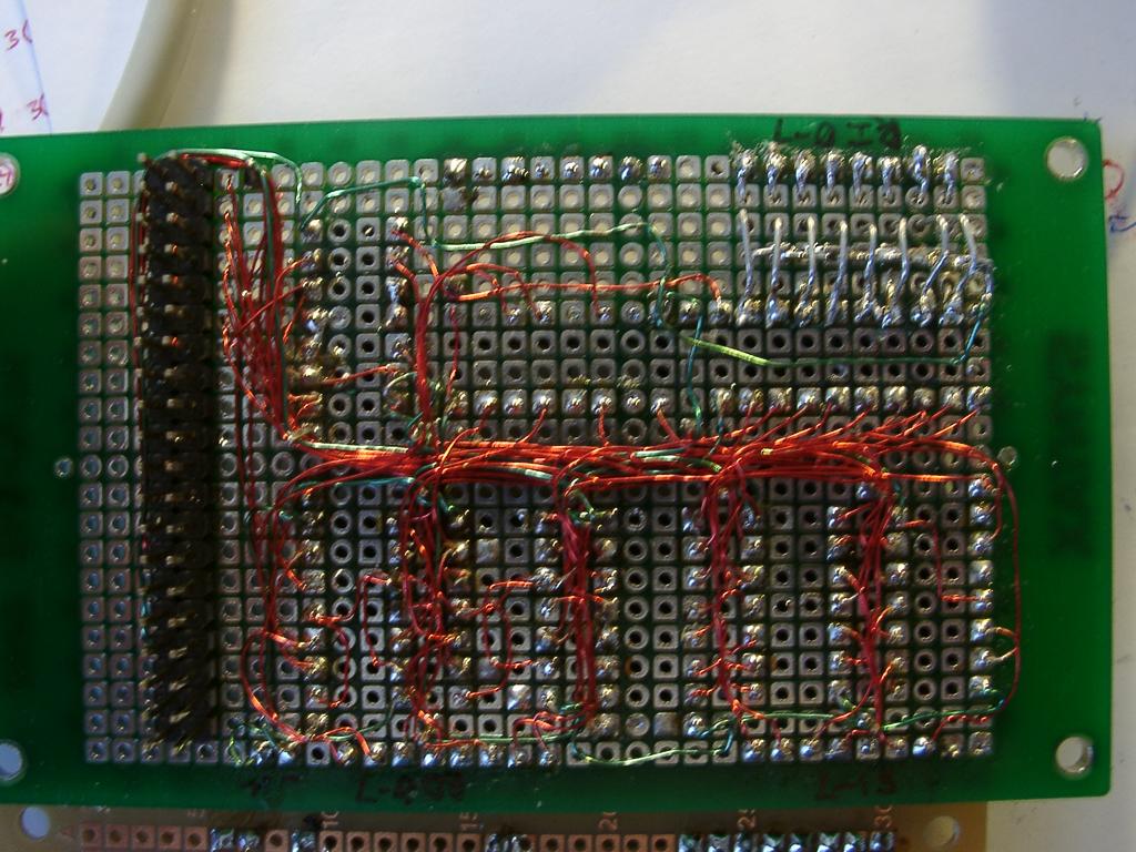
Picture showing where I bridged resistors on the back side of the I/O board
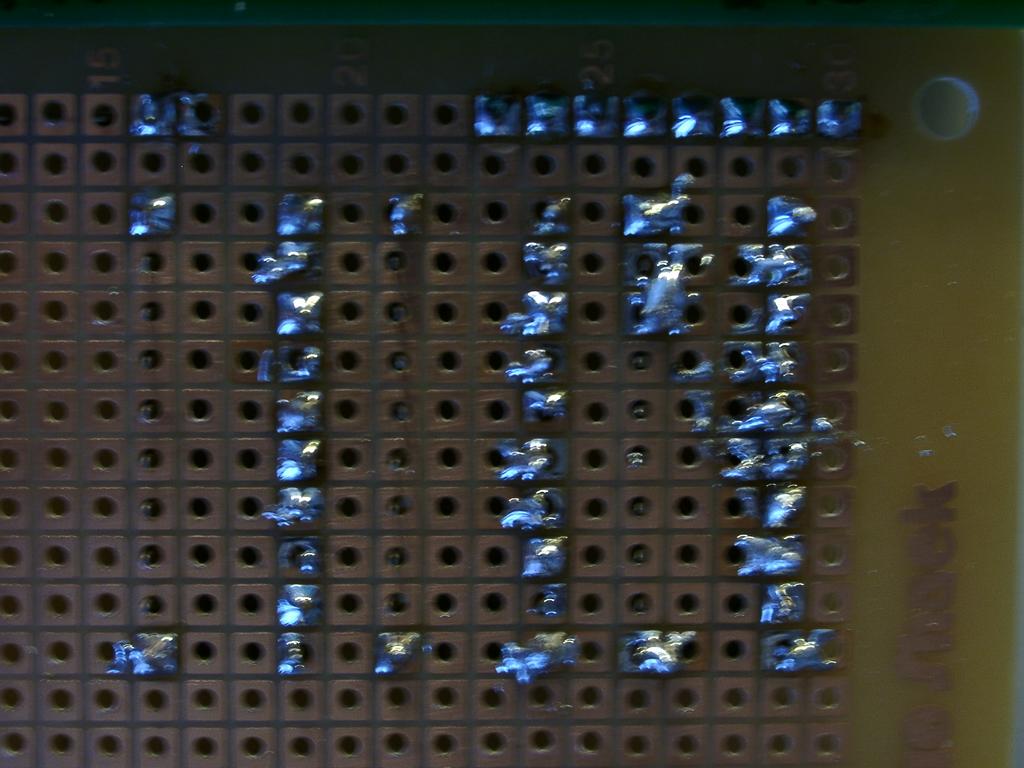
Closeup of the trouble I had soldering the Radio Shack PC board - unlike the other board, it turns out the radio shack terminals needed sanding first to solder well. Thanks to Kerwin for that tip!
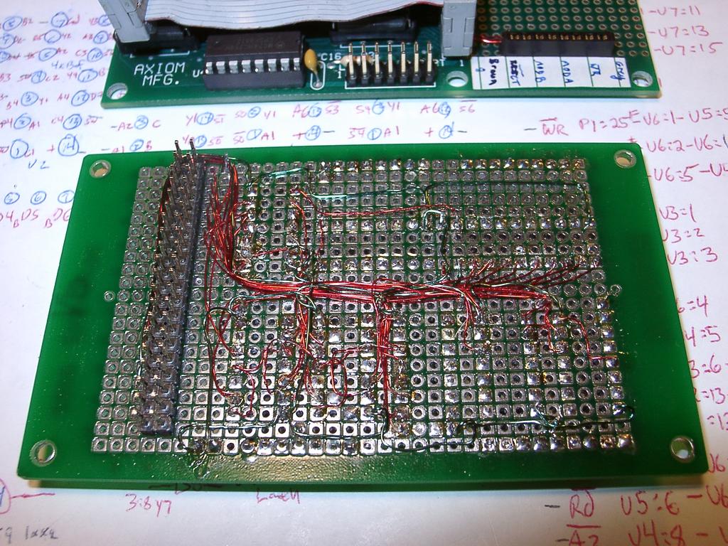
Closer view of the back of the I/O board, featuring the point-to-point wiring
Layout showing final motor control board in progress
back side of I/O board (mostly done) and motor control board (just started)
Closeup of the top of the I/O board. The empty chip is my 6 bit output latch for switch matrix - this chip gave me trouble! I had used a 6 bit chip instead of an 8 bit cip to squeeze it onto the board - but it took me a few tries over quite a number of months to figure out that the latch input was reverse of the 8-bit chip.
Closer view of testing I/O board
View of prototyping motor driving board - yes I can be that anal about laying out wires, but I was going to use this board in an Acroname competition
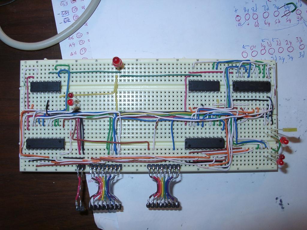
Testing the IO board with prototyped 2 8-bit latches and H-bridges
Thursday, July 01, 2004
Not as close a look at the point-to-point wiring. You can see how I channeled the wires to mostly keep the ICs free, and to keep the layout moderately clean. I did this with posts installed inverted.
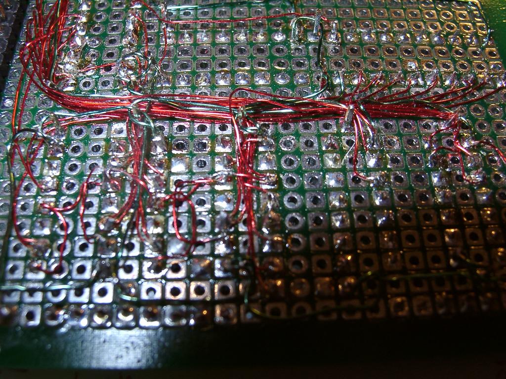
Closeup of the point-to-point wiring of the I/O board - more complete
Wednesday, June 30, 2004
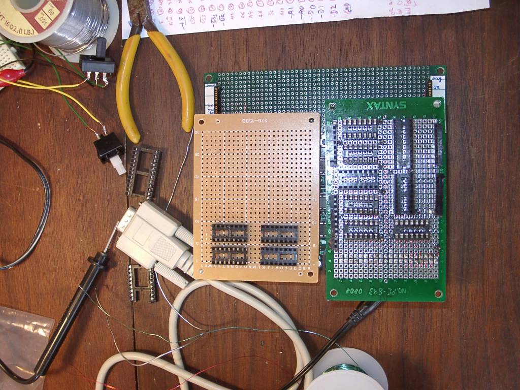
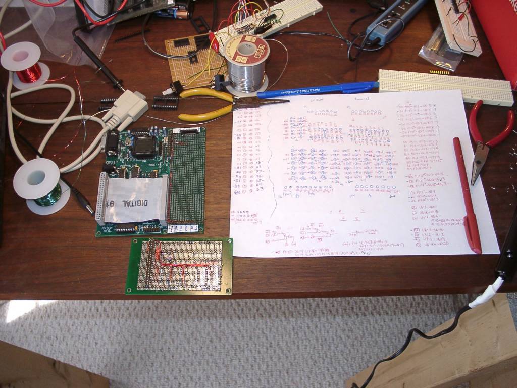
2002-03-30 - Top down view of I/O board and Motor controller board - trail layout
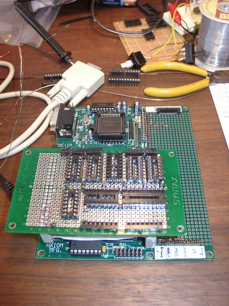
2002-03-30 - Top of I/O board, in it's placement above the HC11 board. Connection to HC11 is via 40-pin ribbon cable.
2002-03-30 - Building up an I/O board to interface with my HC11, and drive a motor driver board
2002-03-30 - Closeup, angle of point-to-point wiring on I/O board
2002-03-30 - Closeup of the I/O board, point-to-point wiring in progress
Monday, June 28, 2004
Testing H-Bridge on Address bus with decoding logic